SEAMLESS-WAVE

SEAMLESS-WAVE is a developing “SoftwarE infrAstructure for Multi-purpose fLood modElling at variouS scaleS” based on "WAVElets" and their versatile properties. The vision behind SEAMLESS-WAVE is to produce an intelligent and holistic modelling framework, which can drastically reduce iterations in building and testing for an optimal model setting, and in controlling the propagation of model-error due to scaling effects and of uncertainty due statistical inputs.
Input file including the positions where water depth and velocity histories are to be extracted (.stage)
This file specifies the locations of points (in X and Y coordinates) where LISFLOOD-FP generates a time series output of water depth and velocities.
For each location specified in this file, water depth (in metre) and velocities (in metre per second) values will be written in two files with the extensions of .stage and .velocity, respectively.
These data will be written at each massint interval (of time in sec.) specified in the .par file. The format of a .stage input file is as follows:
-
Line 1. Number of points at which water depth and velocity output time series are required
-
Line 2. X and Y coordinate of 1st point
-
Line 3. X and Y coordinate of 2nd point
-
…
-
Line n. X and Y coordinate of ith point
Generating the time series output for the water depth is activated by including the stagefile item in the .par file, followed by the name of the .stage file to be read. For further activating time series output for the velocities, the extra item of voutput_stage must be included as well.
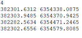
The figure below shows a screenshot of the .stage file used for the Merewether case study, namely merewether.stage, which tells LISFLOOD-FP to write time series output of the water depth values at 4 points inside the domain.
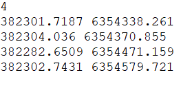
Important note. As mentioned in section “Parameter file (.par)”, in case of the DG2 solver, the DEM must be provided in three separate files with the extensions .dem (for the average-coefficients), .dem1x (for the slope-coefficients in the X direction) and .dem1y (for the slope-coefficients in the Y direction). These three files can be generated manually from a raw DEM file by following the instructions in “Preparing the DG2-related DEM files using generateDG2DEM toolkit”. In case a DG2, ACC, or FV1 simulation run is applied for any or all the DEM files generated by the generateDG2DEM toolkit, all the X and Y coordinates in the .stage input file should be shifted by -dx/2 and +dx/2, respectively. For example, for the Merewether test case at a resolution of dx = 0.175, the X and Y coordinate of the points in .stage file should be modified as shown in the screenshot below.