SEAMLESS-WAVE

SEAMLESS-WAVE is a developing “SoftwarE infrAstructure for Multi-purpose fLood modElling at variouS scaleS” based on "WAVElets" and their versatile properties. The vision behind SEAMLESS-WAVE is to produce an intelligent and holistic modelling framework, which can drastically reduce iterations in building and testing for an optimal model setting, and in controlling the propagation of model-error due to scaling effects and of uncertainty due statistical inputs.
Parameter file (.par)
This is the starting file for setting up and running any simulation. Inside this file, all the required parameters are entered, including the names and location of files of relevance for the case study under consideration. While putting items in the .par file, the following rules apply:
-
Only the items listed in the LISFLOOD user manual are read by the code. Any other item will be ignored.
-
There should only be one item per line. Items can be entered in any order. To comment out a line add a
#in the first character space. -
If an expected item does not appear, the model resorts to the default value specified inside the code, without generating an error message.
To run the 2D ACC, FV1 and DG2 solvers, the following list of items need to be specified in the .par file.
Item name input |
Description | Solver |
|---|---|---|
DEMfile filename |
The file name of the Digital Elevation Model | All |
resroot name |
Root name based on which result files are to be named | All |
dirroot foldername |
Name of the directory where the result files are to be saved | All |
saveint value |
Interval in seconds at which 2D spatial map files are saved | All |
massint value |
Interval in seconds at which the .mass file is written |
All |
sim_time value |
Total length of the simulation (sec.) | All |
initial_tstep value |
Initial guess for the optimum time step and maximum possible time step (sec.) | All |
bcifile filename |
Name of the file for identifying the floodplain boundary condition types | All |
bdyfile filename |
Name of the file containing information on time-varying floodplain boundary conditions | All |
fpfric value |
Manning’s n value for floodplain if spatially uniform | All |
manningfile filename |
Name of the file containing a grid of floodplain n values (Manning’s coefficients). If both fpfric and manningfile items are specified, the values in manningfile will be used and fpfric will be redundant. |
All |
| acceleration | Selects the ACC floodplain solver | ACC |
| fv1 | Selects the FV1 floodplain solver | FV1 |
| dg2 | Selects the DG2 floodplain solver | DG2 |
| cuda | Run the acceleration, FV1 or DG2 solver on a GPU | All |
dynamicrainfile filename |
Name of spatially- and temporally-varying rainfall data (NetCDF) | All |
nodata_elevation value |
Terrain elevation value that replaces NODATA values in the DEMfile | All |
| drain_nodata | Enable to remove water in cells with NODATA elevation | All |
startfile filename |
Name of the initial conditions file with water depth in ARC ascii raster format | All |
startelev filename |
Similar to startfile but with water surface elevation rather than depth (in ARC ascii raster format) | All |
| startq2d | Enables reading initial condition of discharge (in ARC ascii raster format) | All |
stagefile filename |
Name of the file containing the locations of points at which water depth values (time histories) are to be written to a text file at each massint |
All |
gaugefile filename |
Name of file containing the locations of points at which velocity values (time histories) are to be written to a text file at each massint. voutput_stage should also be included to activate this option. |
All |
| elevoff | Suppress production of water surface elevation files (*.elev) |
All |
| voutput | Enable writing out ascii raster files (*.Vx and *.Vy) of the velocity values in the X and Y Cartesian directions |
All |
| voutput_stage | Enable generating the velocity output data in a file specified by gaugefile |
All |
| limitslopes | Enable the DG2 minmod local slope limiter | DG2 |
| krivodonovathresh | Control the localisation of the DG2 slope limiter (Default: 10.0) | DG2 |
| mint_hk | Keyword to allow calculation of maxH (maximum water depth), maxHtm (time of maximum water depth), totalHtm (total inundation time) and initHtm (initial inundation time) at the mass interval rather than every time-step |
All |
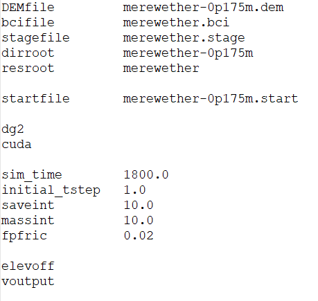
The snapshot below shows the .par file used to set up the Merewether test case, named merewether-0p175m.par.
In case of the DG2 solver, since it relies on piecewise-planar representation based on average coefficients and two slope coefficients along the X and Y directions, three separate files must be provided for each of the DEM and initial condition files: one file containing the average-coefficient values and two extra files containing the slope-coefficient values in X and Y directions (all in Esri ASCII raster format). The user can generate these files manually, from the raw DEM file and a given initial condition file, by following the instructions in “Preparing the DG2-related DEM files using generateDG2DEM toolkit” and “Preparing the DG2-related Initial condition files using generateDG2start toolkit”.
It should be noted that, in the .par file, only the files containing the average-coefficient values need to be specified (i.e. by setting the items DEMfile, startfile or startelev). By doing so, the two extra files that include the slope-coefficient values will be read by the code automatically.